Figure 1: Top View of the System
| Current Prototype | Fourth Prototype | Third Prototype | Second Prototype | First Prototype |
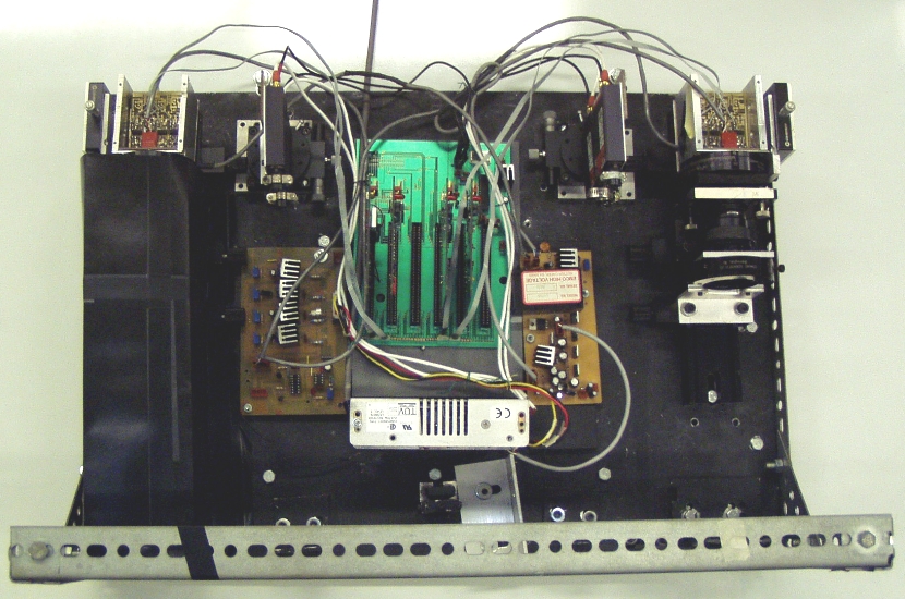
Based on the third prototype the fourth prototype displays some slight overall modifications as can be seen from Figure 1, below. New electronics have been added as well as more laser modules. The lasers now have a new rotating stage to allow for finer rotation adjustment instead of just being bolted down to the base.
Figure 1: Top View of the System
Figure 2, below, gives a general overview of the system. The basic detector unit consists of a laser diode system and a photodiode array positioned above the roadway. The laser system is a pulsed infrared diode with line-generating optics that projects a laser beam onto a road surface. The imaging lens focuses the reflected laser light onto the active area of the sensor array. The signal from a photodiode is amplified and sent to a computer for processing. Vehicle presence is detected based on the absence of the reflected laser light. Two detector units are integrated and placed at a known distance apart. Two pairs of lasers/return optics are used for detecting vehicle presence at two points laterally about 4 and 8 feet across the lane. A sampling rate of about 10 kHz is generally acceptable. Any (threshold) change in the amplitude of the pavement reflectance indicates a vehicle. As seen from the figure, t1 is the time when the first laser line is blocked, t2 is when the second laser line is blocked, t1' is when the first laser is unblocked, and t2' is when the second laser line is unblock. We can calculate the length and the speed of a vehicle with Dref, which is the distance between the two laser lines, t1, t2, t1', and t2'.
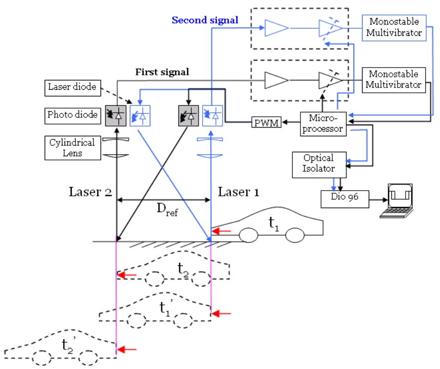
Figure 2: System Overview
Laser and Sensor Optics
Since the optics of the system has not changed much over the past few prototype generations, a more detailed explanation of the optics is availble on the Optical-System page.
Four off-the-shelf integrated high power diode lasers from Power Technology Inc. (model ML20A15-L2) are used in the fourth prototype. this is an integrated laser system that incorporates a DC/DC voltage converter, a voltage regulator, pulse generator, a laser diode, and line generation optics all into one unit. The unit only requires a 12V DC power supply and a trigger pulse for regular operation. Each laser has a peak power output of 20W at 905nm, with a pulse width of 9ns. They can be pulsed up to a maximum rate of 10 kHz. The line generating optics produces a beam having a full fan angle of 15 degrees. The lasers' high performance and compact size make it a good candidate for use in a field deployable prototype system.
A laser producing infrared light (with a 905nm wavelength) was chosen for a number of reasons. Infrared light has good transmittance through fog, which facilitates better performance under a larger range of weather conditions. Furthermore, the intensity of sunlight near that wavelength is at a local minimum, minimizing any noise due to sunlight interference. An infrared laser was also thought to be more appropriate for outdoor use because it is invisible to the human eye, causing no distraction to passing motorists.
The previous prototype only had enough laser power to utilize 4-elements of the APD array. The fourth prototype, with 2 lasers per each sesor, has the ability to utilize up to 8-elements of the the APD and possibly up to 24-elements. This will give the system the ability to give a more accurate profile of the passing vehicle. Each of the laser diode systems produce a single lase line. Two laser diode systems are used to create a longer line with a better power distribution along the length of the laser line.
System Electronics
Since the signal output from the APD array is a very weak fourth signal, a dual stage preamplifier is used to convert the fourth signal into a voltage signal and amplify it from a 9 nano-amp signal to a 2.5 volt signal. The voltage signal goes into a multi-vibration mono-stable oscillator circuit which outputs a 5 Volt pulse when an input pulse occurs. The output pulse then goes into a PIC microprocessor which outputs a digital signal with a high of 5 Volts to a computer when ever the laser is not blocked and a low of 0 Volts when the laser is blocked.
Data Acquisiton System
The PCI-DIO-96 board uses the PCI MITE ASIC to communicate with the PCI bus. The base address and interrupt level for the board are stored inside the PCI MITE at power on. The device driver for the PCI-DIO-96 board finds the board in the PCI bus and configures the register in the board. The I/O port in PCI-DIO-96 is memory mapped.
The system's circuitry can divided into three stages: signal pre-amplification, Microprocessor-based feed-back control signal conditioning, and digital output, as shown in Figure 3, below.
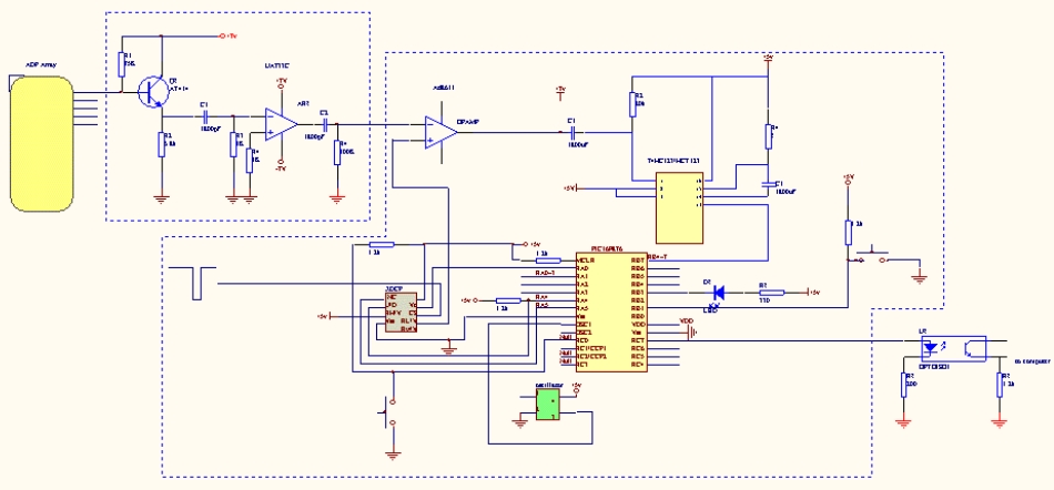
Figure 3: Electronics Overview
Capacitors are used to isolate DC signals between different parts of the circuit, so that a continuous signal can not pass through the circuit. Ambient lights normally generate continuous signals. After intensive testing and adjustment, the interference between different parts of the circuits are reduced to the lowest level, so that the system has a signal/noise ratio 5 times lower than the previous version. The transition time is an important factor to the accuracy and consistency of data measured.
The potentiometers (W1) are used to adjust the sensitivity of the analog circuit output. Since there are eight signal channels in the fourth system, manual adjustment of the potentiometers takes a long time when testing on the highway. Manually adjusting the potentiometers becomes tedious if the system is extended to 48 channels. For convenient adjustment, a microprocessor was introduced into the circuitry to automatically adjust the potentiometers. Using this microprocessor, the adjustment can be done in less than one second. We also expect the accuracy of the adjustment to be much higher than manual adjustment.
The LBDS utilizes a standard power supply that is then fed into multiple DC/DC converters. The power supplied to each side of the LBDS has been separated in order to reduce and effect each side would have on each other. The laser power supply and their timing window signals are created by a microchip.
The LBDS utilizes three different boards in order to take in the signal from the APD array and output the signal to the computer. All board diagrams are located in Appendix A. The main board has 6 slots and a Rabbit processor connector. The Rabbit processor implementation is for future work. The 6 slots are used for the PIC boards. The main board provides the laser source, timing window signals to keep the microchips synchronized with the pulsed laser beam. The PIC boards can easily be plugged into and pulled out of the main board. This allows for easy maintenance, repairs, debugging and expansion. One PIC board contains two PIC microprocessors, 8 digitally controlled potentiometers, 8 reflected signal-timing window signal comparators, mono-stable circuitry, feed-back control circuits, and have end connectors for the signal output to the computer. The output from the laser system goes through the PIC board's computer end connectors that connect to a digital input output board.
The timing window is shown in the Figure 1‑2.7.The signal from preamplifier is compared with a timing window signal which is controlled by the PIC microchip. The down pulse of the timing window signal will be set automatically to a proper bottom value according to the noise and the strength of the reflected signal by the PIC microchip. The AD8611 comparator will generate an input signal for the monostable circuitry. Normally, the signal out of timing-window is at 5 Volts, and the preamplifier signal is less than 1 Volt. So the output of the AD8611 is HIGH. In the timing-window, The reflected signal will come. If the signal is bigger than the bottom of timing-window, the output of AD8611 will be LOW which will cause the output of the monostable is HIGH. If the reflected signal is blocked by vehicle, the element signal from APD is smaller than the bottom of timing-window. The comparator will generate a LOW output which will cause the monostable to output a LOW.
A new APD array is being tested. The new APD arrays are created by Pacific Silicon Sensor. The other APD arrays that we are utilizing are created by EG&G.
Since the sensor circuit outputs are digital signals, an A/D converter is not needed. A general-purpose low-cost digital I/O board (PCI-DIO-96 from National Instruments) is used an interface between the sensor circuitry and the computer system. This digital I/O has 96 channels of configurable input/output, so it is suitable for our system when all 48 channels are required.
Since the outputs of the sensor circuits are digital signals, the A/D converter is no longer needed. A general-purpose low-cost digital I/O board PCI-DIO-96 from National Instruments is used as an input interface between the sensor circuitry and the computer system. This digital I/O has 96 channels of configurable input/output, so it is suitable for our system when all 48 channels of signal are required.
The data acquisition software is used to collect, process and display data from the hardware of the detection system. The data are read from the output of sensor electronic circuit periodically. All tasks have to be done at the same time. However the data are to be acquired in the same interval from the hardware. In other words the data acquisition task should be deterministic, otherwise information will be lost. The concurrence of the deterministic tasks requires real-time performance of the operating system. Previously, a PMAC (Programmable Multi-axis Controller) DSP board and A/D converter were used as the data input device. The data acquisition software is a multi-thread program running in a real-time Lynx operating system. The data from the laser detection system are acquired by the PMAC board in a certain interval and written into a buffer in a dual-ported memory by the device driver. The user level application software reads data from the buffer in the device driver, processes it in different threads to obtain vehicle data, and displays the results in a GUI. The most critical real-time tasks are done primarily by the PMAC board, which is a complete computer system.
Because the implementation of data acquisition using a DSP board makes the system price high, we have been seeking a real-time system to conduct both data acquisition and processing. This board has 96-channel programmable digital. We chose real-time Linux as a platform because it is cost effective and is becoming more and more popular in real-time embedded systems. RT-Linux is one of various real-time Linux systems, and was developed in the Department of Computer Science of the Institute for Mining and Technology of New Mexico by Victor Yodaiken and Michael Barabanov. RT-Linux builds a small kernel directly over the processor, which is independent of the Linux kernel. The Linux kernel runs on the top of this kernel and shares the processor with other RT-tasks. Because of its small kernel, RT-Linux has very good real-time performance as long as the real-time tasks are not too complicated. In our case, the most critical task is to read data from I/O ports in an accurate interval. This task is time-critical but simple, so it is suitable for RT-Linux. In RT-Linux, device drivers are kernel modules that always run before the processes in user space. While data acquisition is carried out in kernel space in real-time mode, the data processing and GUI program can run in the regular Linux OS. Figure 4 shows architecture of the data acquisition. The graphical user interface running on Linux space is shown in the next section of the field-testing results.
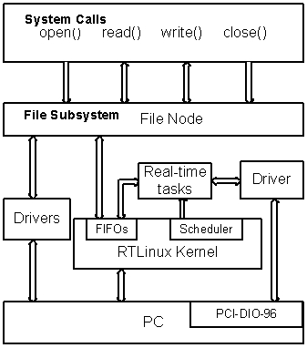
Figure 4: Architectur of the Data Aquisition System
FIFOs are used to communicate and transfer data between the real-time kernel space and user space. Two FIFOs are created as the data buffers. The data are written to the data buffers of two FIFOs in turn in the kernel space. When data in one FIFO are full, the device driver notifies the process in the user space that the data are available through the third FIFO created for synchronization. This FIFO is used to synchronize the data write and read between the kernel space and user space. The fourth FIFO is created to send commands from the user space to the kernel space. These commands will set the sampling rate, and start and stop the sampling thread in the device driver. In the user space the data read is synchronized using the system call of function select.